


PREAMBLE:
After an extensive
analysis of the Fuji, with often quite harsh criticism, this was
an excellent opportunity to compare build qualities of other brands
and see where it all stood. The patient has come in with a faulty
Flash. It refuses to fire and subsequently WON'T allow an external
Flash to work either. Interesting. Nurse .. scalpel ..
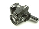
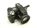
INITIAL COMPARISONS to
the S602 :
It's a tiny bit smaller and "blockier" than the S602
(more square lines). As a tech, I prefer this styling and "solidness"
MUCH more than the S602. The linished magnesium on black is definitely
"cool". If you have big PAWS, then it could feel cramped
though. The alloy construction is definitely a BIG plus, BUT it
goes downhill from there :-). Literally dozens of screws and interlocking
panels are out of control. And dozens of SOLDERED wires?? What
the heck? If the construction was plastic, this multi-section
design would be a nightmare, but it's well machined to fit together.
Even so, it worries me from a service point of view. As this is
the first one I've seen, I don't have any "real" opinion
yet if it's better or worse, just an observation. One thing for
sure, It's going to be a service nightmare pulling it completely
apart *.
NOTE : It is obvious that the design / engineering of the "electronics"
is abysmal to say the least. I am stunned that a respected name
like Nikon could come up with this crap. It's not JUST Nikon either,
I was so disappointed when I first dis-assembled my own Fuji S602
and saw how bad it was. I so wanted to believe that this wonderful
new world of Digital Imaging was about engineering and the beauty
it portrayed. Maybe I'm just too critical, an outdated 'dinasaur',
maybe in this new age we don't question what's "under the
hood" - after all, if it works, why worry? ........ naaaa
BUGGER 'EM !! I'll call them as I see them.
*** I am NOT implying
that this camera won't carry out it's intended design, just don't
bother fixing it.
* Day 4: I've gotten used to the mess :-), so it isn't
bad now. In fact, I can navigate quite easily, thanks to the really
"open" spaces :-)
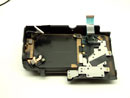
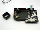
1/ REMOVING THE REAR
1/4 COVER : Difficulty Lvl_2.0
NOTE : FIRST Remove the batteries and FLASH Cards.
There are
7 screws to remove from all around the rear section.
SCREW LOCATIONS:
S1 2x Bottom of case, next to LCD
S2 1x Next to ZOOM-W button
S3 2x Inside CF compartment door, rear wall
S4 1x Left of LCD pivot arm (NOT the one ON the pivot arm, next
left)
S5 1x Left of EVF, next to dioper wheel
NOTE : The EVF rubber surround will need to be removed. It is
only press fitted in, BUT you will need to pry it out slowly so
as NOT to tear the rubber. You may need to loosen other section
screws nearby IF it won't budge or "wiggle" it out while
holding the rear section ajar. It's Not at all too difficult once
you "know" what has to happen.
The REAR SECTION will now come apart quite easily. There are 2
ribbons to unclip R1C3, the LCD and rear-switch
bank. Both are ONLY friction fit i.e. NO levers / arms etc. So
now the back is OFF !! R1C1
and R1C2.
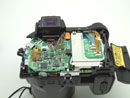
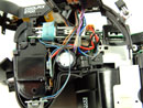
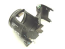
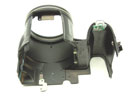
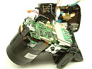
2/ REMOVING TOP SECTION
: Difficulty Lvl_2.0
Note: It can NOT be completely removed, it remains tethered via
a bunch of "soldered" wires !
First remove the 3 ribbon cables that are connected on a PCB glued
to the metal CF cover.
SCREW LOCATIONS:
S10 2x Inside CF compartment, along the front edge.
S11 2x POP the Flash by hand, front edge of the cover plate.
S12 1x Deep inside the Battery compartment, near the TOP of the
camera.
S13 1x Hidden under the COOLPIX 5700 Logo on the front. Peel back
the corner of the rubber which is held by a bung.
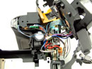
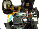
Gently pull the TOP section back and up. UNCLIP a large yellow
ribbon cable (to centre of PCB stack). Note : The TOP section
doesn't come off. It is SOLDERED to various PCB's in the Internal
stack !! I would love to meet the engineer who designed this,
I want to introduce his testicles to a car battery !! All the
Flash wiring is soldered, some deep down inside ! Will confirm
later.
I noticed one solder joint was very poorly done, but I DOUBT it
is responsible for the fault.
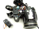
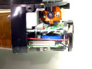
3/ REMOVING THE EVF
: Difficulty Lvl_2.0
S15 2x EVF
mounting feet screws, easy to find.
Undo 1 ribbon cable and 1 power cable, both are friction fit.
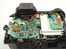
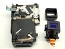
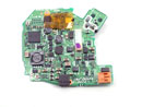
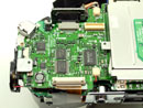
4/ REMOVING the Power
PCB : Difficulty Lvl_1.0
SCREW LOCATIONS:
S18 Only one at the bottom left edge.
The PCB is levered out from the TOP right. Only a stacking connector
holds it in place. Refer R3C2.
There are several fuses, as seen in R3C1, R3C2. NOT all are marked.
Unfortunately these are NON-RESETTABLE type and quite over-rated
because of that. They are Surface mount type 0805 size (damn tiny)
and rated at mostly 2A !! The reason they over-rate them so much
is - you DON'T want them blowing UNLESS it's an emergency ! As
they're not easy to replace, it's pointless having them. In this
day and age, EVERYONE uses Polyfuses (auto-resetting). At first
I had high hopes that I'd found the fault, but all fuses were
ok. A scan of other components found a SHORTED Tantalum (near
the Battery connector), but that turned out to be the old DC power
connector debarkle*.
*The world has mostly standardised on centre +VE for DC type Power
connectors. Unfortunately, the DC sockets are switched BODY or
--VE (because some engineer was too lazy to design it properly).
So now we have BATT +VE and DC +VE tied together with --VE being
switched. As it ISN'T a change-over, all sorts of "tricks"
are used to isolate the 2 supplies, SHOTTKY's, FETS etc. Just
another mess. The Fuji is the same.
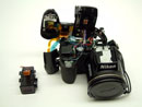
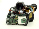
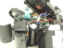
5/ SPLITTING the BODY
: Difficulty Lvl_3.0
SCREW LOCATIONS:
S20 ALL of the REST, eveything you can find :-).
Third stage
conclusion - AAEEEIIIIeeeeEEEEAAAAeeeeeaaaaRRGHHHH !
| |
|
|
|
|
|
|
|
|
|
 |
 |
 |
 |
 |
|
|
|
|
|
 |
 |
 |
 |
 |
|
|
|
|
|
 |
 |
 |
 |
 |
|
|
|
|
|
 |
 |
 |
 |
 |
|
|
|
|
|