Blank
Blank
Blank
Blank
Blank

Blank
Blank
Blank
Blank
Blank


The S3800 (S3000) is a VERY PLEASANT camera to work on. The Lens
build quality is excellent and it is very well laid out inside.
Naturally, there's always a technical gripe or two :-) . In this
case -
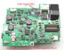
(a) The RTC battery is useless (or the charge circuit is crap)
! They are forever failing, and even when I bought a NEW P/S PCB
(because I couldn't be bothered adapting a different type) ..
IT FAILED a short time after. I assume Fuji made ONE run of stock
when the cammie was first manufactured, so ALL batteries now are
EOL. Oh well, back to soldering fly leads !
(b) The dumb idea of making the Switch actuactors part of the
Plastic Case and HOPING like hell that they make on the teeny
(~1mm tolerance) switches on the PCBs. IF the Body was Rigid and
unflexible, it might have been a good idea, but it's NOT. So,
in time, as there is wear and movement (The Control PCB isn't
even screwed on, it just clips in), they start "slipping".
I've just finished wasting 2 days on one, swapping parts until
I finally got it right ... ie NO intermittant shutdowns.
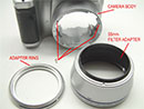
(c) The 3 screws that hold the front Lens Cover Ring on, come
loose easily. Probably the biggest complaint I've had with this
cammie.
So if that's all I can say thats bad about it, we're DOING WELL
!!
(Note: R2C5 referes to Pic @ Row_2 Column_5)
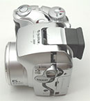
1/ Removing the Rear
Cover : Difficulty Lvl_0.5
NOTE : FIRST Remove the batteries and FLASH Cards.
There's 5 (or 6 , I forgot and too lazy to check) screws to remove,
all easy. Popping the Rear case is a bit trickier. The easiest
way Is probably to use your nails to "crack" it open,
then run along the seam. Refer Fig_R1C2
Theres just 1 ribbon
to unclip.
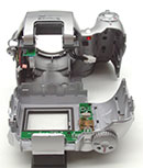
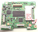
2/ Next, remove 2 screws taht hold the LCD, which then swings
FOWARD and unclips.
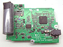
Next remove the CPU PCB. There are a few ribbon cables to remove
and a couple of plugs . The ribbon cables are mostly FRICTION
FIT. ie You just pull them out. I use either my fingers, Flat
nosed pliers or Long nosed pliers, whatever is easier. The LCD
IS a Locking Lever type. the CPU PCB is then pulled UP off the
(lower P/S PCB) stacking connector and swings Foward to gain access
to the Control ribbon.
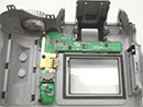
3/ Next, remove 2 screws to free the P/S PCB. You should then
Unplug the Battery connector and PRY it gently out of its Holder.
Also, unfurl the CCD ribbon from around the Flash charge capacitor.
Undo a few plugs and stuff and the P/S PCB come sout easily.
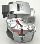
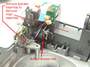
4/ There are just 3 screws holding the Lens Module in. One holds
an earthing strap, so don't forget it later. The Lens then just
drops out. THEN you can get to the 3 DAMN screws that hold that
front Lens Ring ON !!!! :-)
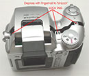
Not a lot goes wrong with this cammie. IF you have Intermittant
shutdown problems, check the clearances of the PCB mounted Control
switches (wrt the Plastic Tabs on the body). OK thats enough for
today.
Detailed Pix (with notes) can be found at - http://www.pbase.com/digsys/fujis3800
| |
|
|
|
|
|
|
|
|
|
| |
|
|
|
|
|
|
|
|
|
| |
|
|
|
|
|
|
|
|
|
|
|
|
|
|