FUJI
S602Z : NOTES
DIS-ASSEMBLING THE S602Z
...... 10
April 2006
Link to CCD+Lens and Home Page
WHY ? Because it wanted me
to.
- Sorry for the quality
of some PIX. They were taken with a Canon G2. Even with 4 hrs
of fiddling, I could NOT get it to take decent shot, beats me
how anyone can like that camera.
PRELUDE: 3
Years on
It is now over 3
years later, and having now seen inside other brands, my opinions
have changed markedly (I originally bagged the heck out of Fuji)...
there are FAR worse designed models out there, both in build quality
and support. So I've revised my "opinion" of the S602
(S7000 and S20 would be similar) ... Build Quality is Average,
Lens design is still Pathetic. Fortunately, its a great camera.
My S602 is STILL clicking away without incident, EVEN after the
hard life it's had and several open-heart surgeries :-). I have,
like many others, been keeping an eye out for a worthy replacement
and STILL can't find one. The S20 Pro was a hopeful, but the idiots
removed 5fps TIFF (Raw would've been better) and the BIN function.
For sports "shooters", that's just plain lunacy. I'm
afraid our fearless leaders have suffered a stroke and are just
paddling around aimlessly. When will these cretins give us "Firmware
upgrades" !! or let US do our OWN !!
OK, Enough bitching, back to business.
I never did do the "updates" I was going to do. Too
many lost interest along the way and I got lazy :-). I have nearly
finished a few projects though. Maybe I'll get a new spark in
2006 :-) .... And that's it for the first 3 years
My love of electronics started one fateful day in 1968 when my
old man said to me -
"Jimmy, U a smarta boy. Go fixa the damn TV"
I removed the cover of our aging black+white TV and noticed a
pretty RED wire. A second later I was belted against the wall.
Repeated attempts to touch "glowing" glass tubes, funny
looking disks etc ALL met with the same result. I was in love
!! Some say I haven't learned nothing since :-) PPFFTTT
1/ REMOVING THE REAR
3/4 COVER : Difficulty Lvl_2 ... Note: R2C5
referes to Pic @ Row_2 Column_5
NOTE : FIRST Remove the batteries and FLASH Cards.
There are
8 screws to remove from all around the rear section. All are the
same length except 1 (above the Flash compartment).
LOCATIONS:
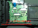
1x Inside USB door
2x Bottom Rear of Case
1x Bottom Middle of Case
1x Above Flash CARD Compartment
1x Inside bottom of Flash CARD Compartment
2x Below EVF (push the EVF rubber out of way)
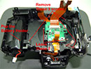
Gently pry
open the back, which is held in place by tabs. It is easiest to
hold the camera upside-down and drop the rear section down.
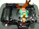
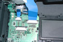
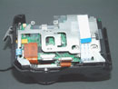
Unclip 2x ribbon cables which HOLD the assembly to the main PCB
_ Take care not to STRESS these as they are quite Fragile !! Bending
them too much will "crack" the conductive tracks. (Yep
done that). Also note that the conductive tracks seem to be PRINTED,
and flaky as hell. If you want to to check connectivity, leave
them plugged into the connectors. Probing the conductor WILL DAMAGE
IT. (Yep done that too). Update: It seems that this was
just a bad batch problem. I only occasionally encounter the fault
now.
**NOTE: To remove ribbon cables, POP OUT the 2 retainers (at each
end of the connector).
UNCLIP the
Rear LCD Ribbon Connector and mini power connector.
To remove the LCD, VERY
CAREFULLY
PRY it from a steel holder with your fingers. The rear section
is a fragile EL plate, and can easily be cracked .. so DON'T twist
or bend it, or try to pry it out with a screwdriver. I use small
pliers to bend the retaining clip out first, remove the LCD, then
ReFORM the clip. It's not spring steel, just soft cr@ppy metal,
so it bends easily.
From here -
- You can clean, check Rear LCD.
- Service, check any Rear Panel switches Including Selector wheel.
- Look at the mess of connectors inside :-)
- Bugger all else
No Major CHIPS
visible from here, just the usual "glue logic".
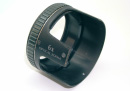
2/ REMOVING the OUTER
LENS BARREL COVER : Difficulty Lvl_0.2 ---- NOT required to Dismantle
the Camera.
There are only
3 screws to Remove from around the REAR of the LENS (actually
3 in the front section and 3 in the rear section).
LOCATIONS:
1x Bottom Rear of LENS
1x Top (Power side) Rear of Lens
1x Top (Outside) Rear of Lens
Gently pry
/ wiggle LENS Cover away from LENS Internal Assembly. When re-assembling,
jiggle the Focus ring so the 2 gears MESH easily (This will make
sure the Outer Toothed Ring meshes with the Drive Ring. It won't
cause any damage, you just won't have Manual Focus.) . ** There
are NO Connections to worry about.
From here-
- You can clean, FIX the FOCUS DRIVE COG (The ZOOM drive is sealed
in the Lens assembly)
- Clean out dust build up
- Use air pressure to blow out dust on the CCD or INNER LENS group.
NOTE: It is
MUCH more effective to remove the Front Glass cover ring if you
want to get to the dust. This cover is only held by double-sided
tape and can be GENTLY pried away using a small flat screwdriver.
More in the dust removal section.
- Bugger all else
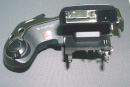
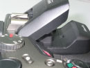
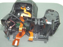
3/ REMOVING TOP COVER
ASSEMBLY : Difficulty Lvl_4
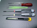
First, you
will need a long sharp scribe (or dentist's pick tool) .. 2 is
preferred. Also if you don't have perfect eyesight, a magnifying
lens is desirable.
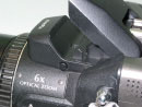
Referring to Fig_R4C1 and R4C2, pop-out the Flash Focus cover via the 2 tabs at
the top. They are located at the corners. Fig_D3 shows the cover
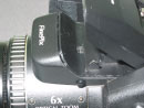
once it's "popped". Remove the cover. Notice the IR
Focus LED alignment screw in the center, Fig_R4C4. DO NOT adjust it unless you need to re-align the
IR sensors. However, it's an easy set-up if you do need to (like
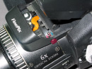
I had to :-) ). Now referring to Fig_R4C4, pop-out the 2 tabs from of the Flash Release Button.
The P/Button is shown in red (blue=hidden). NOTE: I had to modify
mine with a trusty DREMMEL (early production version?), so you
will NOT see anything but 2 TINY tabs. UPDATE: MOST models NOW have a cut out
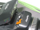
section so it's much easier to get to. Once both are popped, the P/Button will
spring out. The tabs are Horizontal. The exposed cavity is shown
in Fig_R4C5. Remove the 2 OUTSIDE
screws which hold 2 long SUPPORT ARMS.
Unclip the Top Section from around the Power Switch by squeezing
it. The tabs are Internal but easy to pop out. Figs R2C2-C5 and Fig_R3C1 show what the dismantled Section will look like.
OK and Fig_R3C5. OK yeah technically
also Fig_R3C3 and R3C5, for crying out loud. Once all the tabs have been
released, carefully pull the top assembly BACK and UP away from
the Flash Head NOTE:
You will need to move it back 1/4 inch (to clear the support arms)
before it can be swung up. You can only move it about an inch as there are
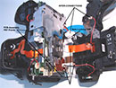
SEVERAL ribbons and plugs to undo. Refer R7C4. Most of these are straight-forward Except 1. It's
the Large HV power connector, you need to press the LOCK Lever
to release it !! Putting this section back CAN be a little bit
harder. You need to watch that the cables don't foul the Flash
release CLIP !! Do a dry run before you screw anything together
ie Push the Flash down making sure it holds and releases ok.
From here -
- You can look at the power switch assembly (it's sealed).
- Check several ribbons, connectors and cables for correct insertion
etc.
- Wonder what the FOOK you're doing :-)
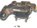
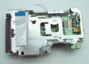
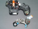
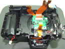
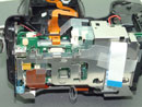
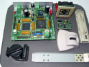
4/ REMOVING MAIN PCB
SUB-ASSEMBLY : Difficulty Lvl_1
Again, we have
a few ribbon cables and plugs to remove, and most are straight-foward
again, except ONE !!
Refer Fig_R3C3, this stupid connector
is EASY to break thus rendering
it useless, but it can be opened (I broke my very first one, but
glued it back ok .. messy, but it worked fine). Don't look at
me, I didn't design it. You WILL NEED a magnifying lens, a very
sharp blade and a "pick" tool or 2 AND 5 hands if you
are an octopus. The "locking bar" (shown in RED) actually
pops UP in this case. Gently bend the "locking tabs"
(blue) away while prying the locking bar UP (gently). The plastic
is soft so you should have enough margin NOT to snap it. Refer
R7C4 for InterConnects.
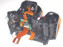
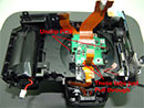
The main PCB module just pries out at 2 places. Pry away at the
DC power Socket and 2 long plastic arms behind the module (Pix
coming).
TBC
Your Disassembled camera should now look like Fig_R1C3. If it looks MORE like Fig_R8C5, then you're in deep shit.
5/ ON to the CCD : Difficulty
Lvl_1.5
In 3+ years,
MANY MANY people have removed and cleaned the CCD and/or IR Lens.
A few have even split the Lens and got it back together perfectly.
I've ripped CCDs in and out a few dozen times now as well, even
unsoldered and repaired faults on the CCD PCB. My point is - everyone
and his dog has done it, so there's no special or pioneering skills
needed any more. Its NO longer a daunting task.
** UPDATE : 17 April
2006 : Refer
R8C2 and R8C3
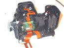
It is definitely easier to Keep the Lens Holding Bracket WITH
the Lens when removing the Assembly. Its a bit more work, but
less stress than trying to PRY the Lens body away from the Outer
lens cover. The Flexi ribbon (IR assembly) is just PULLED through
the slot.
HINT : When attempting to get it back in, simply cut a rectangular
flat piece of platic - slide it through the slot, then push the
ribbon back up using the plastic as a guide. Very easy.
One users
"notes".
"Once the camera has been disassembled, the next step is
to remove the little card at the center of the body.
Then there are two screws that hold the lens assembly to the body.
But the lens assembly won't actually come out until you remove
3 more screws which are fairly obvious.
This loosens things up enough to allow the lens assembly to come
out.
The CCD is mounted to the back of the lens assembly.
It is held in place by a metal bracket.
I was only able to loosen one of the screws on the bracket (they're
VERY tight), but then I was able to swing the bracket out of the
way and extract the CCD chip.
The chip is of course mounted to flexboard and has a piece of
pink glass attached to it.
This is the surface to be cleaned.
I also sprayed inside the lens area with canned air, and discovered
that there's a small optical gasket inside there.
I had to carefully reposition it before putting the CCD back in
place.
That's all, thanks again! "
SEE ALSO :
Other sites
that have "service" information on 4900 and 6900 : (The
lens / CCD is very similar)
- http://www.geocities.com/theolumens/uitelkaar.html
- http://www.camerashed.co.uk/
SUMMARY, NOTES and some
dribble:
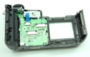
- You can split both halves of the PCB Assembly quite easily.
NONE of the MAJOR IC's are visible at all. The MAIN CPU, Flash
and Cache is buried under the CF and SM Holder. To get to these
you need to unsolder a few S/M micro-connections.
- The Firing switch is sealed and glued by a steel plate, so it's
impossible to solder "pick_off" wires with the intention
of making an REMOTE electronic trigger (main reason I went in).
- There is NO JTAG or other Development Connector visible anywhere,
so "live Emulation" is OUT - forget code changes.
- If you are careful and have reasonable dexterity, there should
be NO reason that you can't perform your own service. In 2 years,
many hundreds have done so, using these guides. MANY of the Fuji
prosumer models are very similar as well. The S7000 and S20 Pro
are practically identical, just with added racing stipes and spoiler
:-)
- The build quality is barely adequate, so if you've been thinking
of Extended warranty ... GET IT. Because of my many Motorcross
shoots, I had the chance to remove a LOT of dust from inside.
There are EASY migration paths via the CF slots and Battery Compartment,
so DON'T rely on it being fully sealed. An example of the build
quality is the LCD holder. Once you lever it out, the metal is
deformed (NO spring tension). When you clip it back, you have
to CLAMP it together (I used pliers) and hold it for 30 secs to
set the tension again, otherwise it can fall out. Note: Preforming it (ie
overbending it a touch) is a simpler method.
- What did I learn ? Dis-appointment and the Decline of Standards
:-)
PLEASE NOTE: All PIX are stored at www.pbase.com/digsys/s602z
 |
 |
 |
 |
 |
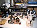
OPERATING
THEATER
|
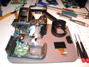
REAR
ASS'M REMOVED
|
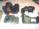
MAJOR
COMPONENTS
|
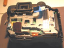
MAIN BODY
_1
|
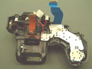
MAIN
BODY - RAW
|
 |
 |
 |
 |
 |
REAR
ASSEMBLY
|
MAIN
ASSEMBLY_1
|
MAIN
ASSEMBLY_2
|
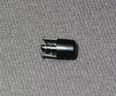
BROKEN
FLASH PIECE
|
TOP
ASSEMBLY
|
 |
 |
 |
 |
 |
W/ FLASH
P/BUTTON
|
FRONT
LENS COVER
|
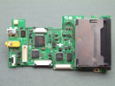
PCB
MODULE - REAR
|
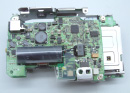
MAIN
PCB MODULE
|
TOP
ASSEMBLY AGAIN
|
 |
 |
 |
 |
 |
FOCUS COVER_1
|
FOCUS
COVER_2
|
FOCUS
COVER AJAR
|
FLASH
PB CAVITY_1
|
FLASH
PB CAVITY_2
|
 |
 |
 |
 |
 |
REAR
PANEL
|
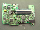
POWER
PCB_TOP
|
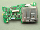
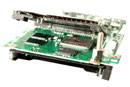
MAIN
PCB_TOP
|
MAIN PCB
ASSEMBLY
|
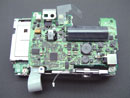
MAIN
PCB_BOTTOM
|
 |
 |
 |
 |
 |
SWITCH
ASSEMBLY I/F
|
MPU,
DRAM, FLASH
|
TOP
ASSEMBLY
|
SWITCH
SUB-PCB
|
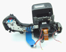
MAIN
ASSEMBLY
|
 |
 |
 |
 |
 |
MAIN ASSEMBLY_2
|
MAIN
UNIT_BULK
|
MAIN
UNIT_2
|
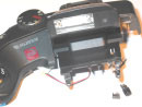
INTER-CONNECTIONS
|
CALM
SCENERY
|
 |
 |
 |
 |
 |
FLASH
RELEASE PB
|
LENS REMOVAL_P1
|
LENS REMOVAL_P2
|
TOOL
KIT
|
ALTERNATE
DISASSEMBLY
|
FOR ANY ENQUIRIES Please email me at
jkirk@digsys.com.au