FUJI
S602Z : PART_3
The CCD / IR Filter
and Splitting the LENS ...... 10 April 2006
Links to Main Disassembly : Home Page
GETTING CLOSER
:
After several
repairs, it's actually getting quite easy now. I can do a complete
strip-down and re-assemble in approx 30 mins. It may not function,
but at least all the parts are stuffed back in :-) .... Just kidding.
Getting to the CCD is quite easy, with only 1 delicate operation
to worry about. After THAT, it's a whole different story. In fact
I'll have to increase the difficulty Lvl scale to 20 !! :-) Fortunately
I had 3 total write-off lenses to experiment with. The Lens and
CCD can only be bought as a unit, a small mercy.
I often wonder if the engineers who design this shit can sleep
well at night? Anyway, on we go ..
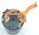
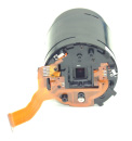
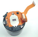
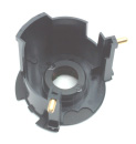
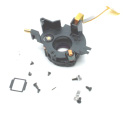
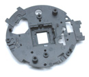
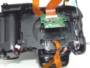
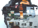
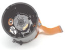
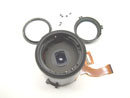
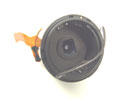
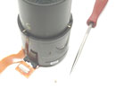
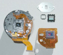
1/ REMOVING THE CCD :
Difficulty Lvl_2.0
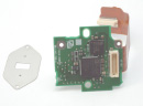
First, unclip
the CCD InterFace PCB (no tools required) R4C3, R4C5 and pry off the main CCD ribbon connector
on the rear (a little bit fiddly). There are just 2 screws to
remove, that hold the entire LENS / CCD assembly to the Main Frame.
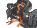
Here it's more fiddly. The Lens / CCD just slides out but 2 "FEET"
catch on protrusions in the cavity, so they need to be pried away.
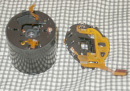
The plastic will deform a bit, but it's fine. It's not hard to
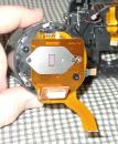
find the offending object. Remove 2 screws that hold a steel CCD
cover plate R1C5
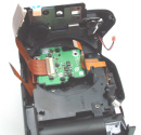
and pop out
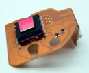
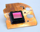
the CCD assembly. At this point, all is easy, and you can remove
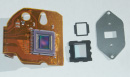
the IR filter to clean the CCD R8C3, R8C4. An interesting Note - with the IR Filter in place,
there should be NO way dust can land on the CCD, so make SURE
you're certain that the dust IS on the CCD !!
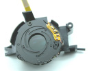
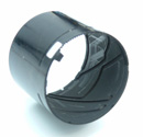
2/ SPLITTING the LENS
: Main body - Difficulty Lvl_5 , Front Assembly - Difficulty Lvl_20
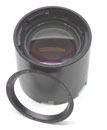
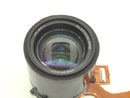
SOME GOOD NEWS before we start ! The Front glass can be removed VERY easily
R5C3, R5C4,
R5C5.
Using a thin flat-wide screwdriver or similar, gently pry UP the
Front Lens cover. It is only held on with double sided tape. Once
removed, there are 3 screws that come out easily. The Front glass
now literally falls out. Note the orientation of the glass as
it can ONLY go back one way (saves having to pull it out again).
MORE IMPORTANTLY, note the number of "O" rings and where
they come from. NOT all screws will have an "O" ring.
My belief is that these are used to adjust the "skew"
of the lens to give a perpendicular focal plane. There is NO service
adjustment or servo for "skew" alignment so I assume
the front glass is simply dropped in and spacers are manually
added to get the best result. It can't be too critical as there
is so much "slop" in the "middle" Focus lens.
One user has already "calibrated" his Focal plane by
tensioning these screws.
You can then clean the Inside surface and the Front focussing
glass. Use an antistatic spray like VDU99 by CRC (I swear by it).
As some have found - OFTEN after normal cleaning, once the glass
is put back in, it just picks up more SHIT from inside (due to
static), so it's worth the effort. Either way, you should end
up with MUCH less dust. Some users have gone to the trouble to
"swab" the inside of the Lens cavity with a QTIP (dipped
in alcohol) to pick up the loose particles. They found so much
grime etc, they gave up. There are too many "hideouts"
for it to collect, so I'd advise NOT to push your luck :-) It
won't be worth it.
Removing the Front glass
will be necessary in order to split the 2 Lens sections apart.
Refer R5C3, One of the Guide rods has an END CAP and there is
NO other way to get access to it. BUT you shouldn't be attempting
this, unless the lens "is" a total write-off anyway.
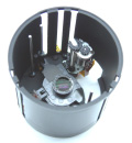
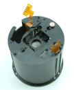
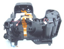
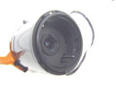
Now back to the Main Lens body R1C1.
Cover the Gap left by the CCD with a piece of paper and tape it
on (Protection from dropping stuff INTO the LENS !!). Use solder
braid to unsolder 3 ribbon Junctions as marked. The ribbon is
VERY tough so don't panic about heat - 300-310oC is fine. Remove
4 screws as marked. Twist the TOP COVER PLATE CW to Unlock it
and Pull it away slowly. 3 of the ribbons will REMAIN with the
Front section R2C3.
Now it gets VERY messy and fiddly. After 3 tries, I stilll haven't
succeeded in putting one back together correctly. In my defence,
your honour, they did arrive damaged !! Somwhere out there ONE
lone soul has achieved it, so there's hope :-) Next patient, I'll
definitely work it out !!
SPLITTING the
LENS : Without dismantling the camera !!!!
- Our first KEYHOLE SURGERY !!
One Note before we start : IF you screw anything up, we CAN NOT
get lens components as spares from Fuji !! It's the complete CCD+LENS
at ~US$350 !! So READ these damn notes BEFORE you start !!
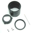
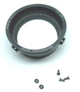
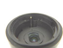
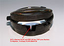
1/ Remove the cover-plate by gently prying it off R6C2. Use a 5mm (say) THIN Flat screwdriver
and work slowly around the circumference. It is only held on by
double-sided tape so you can feel it give.
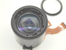
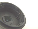
2/ Unscrew the 3 screws holding the front glass R6C3. DO NOT drop them into the inner lens OR turn the
LENS assembly over. The front glass can now be removed easily.
NOTICE how many "O" rings are used and their position,
you will need to put these back exactly as found them. They "set"
the focal plane alignment !! If you F*ck it up, it just means
trying all the combinations until you get "perfect"
alignment.
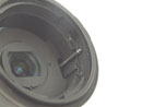
3/ Remove the end cap of the guide rod shown in R6C4 and
R6C5. This
is DELICATE !! IF you simply try to pull it off, you will pull
the rod out of it's base. Yes, it can be tapped back in, but try
to avoid having to do it. Use a SHARP pair of side-cutters at
the JOIN, to slowly wedge the cap off. You can use a pair of long-nosed
pliers or similar to HOLD the base of the rod as security R7C1.
4/ VERY GENTLY and SLOWLY, peel off the dust guard fabric WITH
it's double-sided adhesive R7C2
and R7C3. Peel them away as a
PAIR and do it SLOWLY otherwise you'll STRETCH it !! which means
it won't seal 100% when you assemble it (NOT that the bloody lens
is sealed anyway BUT it gives me something to yell at you about
:-)).
You can see the "culprit" that caused this users problem
R7C2. One of the Inner guide
"sleeves" had fallen OFF it's "guide pin"
and fallen out. It's the second most common fault of a dropped
cam !
5/ Grab the Front lens section from inside (where the Front glass
was mounted) and, while holding the base section in your other
hand, twist it SLOWLY anti-clockwise R7C4. You will hear the gears WHIRR as the front section
extends outwards. DO IT SLOWLY as you can STRIP the gears or cause
them jump OUT of mesh. The "Zoom-OUT" movement is achieved
by twisting anti-clockwise at first, then as you feel the gears
WHIRR, apply gentle outward force AS WELL. Internal moulded SPIRAL
grooves will control the action. STOP AS SOON as you "feel"
that FOWARD movement has ceased R7C5.
This is the "Parked" position when you first start up
the camera. You can see that you are at the end of travel because
the guide pins have just about come OFF the Inner sleeve. The
cap we removed STOPS the Focus assembly falling OUT !!
6/ NOW as you continue to twist the Front lens section anti-clockwise,
you'll notice the ZOOM / FOCUS assembly moves foward !! Keep rotating
until it stops. At this point you should see that ALL 6 brass
guide sleeves are CLEARLY visible and unobstructed (from the "outside").
7/ Mark all 6 slots (#1-to #6), on both the Outer and Inner lens
sections. Mark #1 as the middle one of the ONLY cluster of 3,
then proceed clockwise. That way we are ALL sync'd. The next bit
is delicate. You will have to "POP" guide sleeves #2,
#4 and #6 past a small Internal LIP R8C2 and R8C3. Keep the lens VERTICAL
at ALL times. You will need to "flex" the outer barrel
for each sleeve. POP them one at a time and have them STAY / REST
in the groove as you proceed to the next one. I use a long thin
scribe tool to "pry" the sleeves out.
8/ The Front lens can now be removed. Take it off slowly, so as
not to drop the guide sleeves. NOTE the orientation of the guide
sleeves -- the thicker section FITS over guide PIN while the rounded
section RUNS along the SPIRAL GROOVE.
9/ Next the Inner ZOOM / FOCUS section is removed, in a similar
manner. There are only 2 guide sleeves to POP thsi time.
4/ SPLITTING the Front
GLASS : Difficulty Lvl_1 : *
added 9 April 2006
The Front glass is
actually made up of 2 parts, one convex and one concave. They
are simply held together by a plastic moulding. There have been
a few cases of stains occuring at this junction, usually from
water vapour (heat + humidity) or from being dunked in a river.
This is an easy fix. Remove the Front Glass (as detailed elsewhere),
cut a small notch as shown in R8C4,
and gently pry the 2 halves apart. Be CAREFUL in cleaning the
surfaces, as they are coated ie from physical damage. Once clean,
simply SNAP the Lens back in. You can blacken / fill-in the gap
if you want, but I haven't seen any ill effects if you don't.
That EASY.
PLEASE NOTE: Due to high Traffic, Exploded Views have been moved
to my gallery at www.pbase.com/digsys/s602z
 |
 |
 |
 |
 |
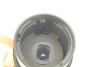
Lens without
CCD
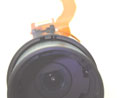
|
CCD with
IR Filter
|
CCD Pre-process
PCB
|
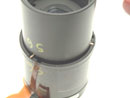
Lens assembly2
|
CCD+LENS
complete
|
 |
 |
 |
 |
 |
CCD+ IR
again .. zzzz
|
Outer Zoom
barrel
|
Outer Zoom
- rear view
|
Inner Focus
assembly
|
Aperture
- Wide open
|
 |
 |
 |
 |
 |
Aperture
servos + bits
|
Focus or
Zoom Motor?
|
CCD Holding
plate
|
Zoom Guide
slots
|
Nekkid
Frame - rear
|
 |
 |
 |
 |
 |
Nekkid
Frame - Front
|
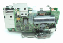
Main PCB
assembly
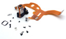
|
CCD InterFace-PCB
|
View of
CCD connector
|
Another
damn view
|
 |
 |
 |
 |
 |
Ribbon
layouts
|
Nothing
here
|
Front glass
w/guide rod
|
Front glass
cover
|
Front glass
assembly
|
 |
 |
 |
 |
 |
FULL Lens
Assembled
|
Front cover
Removed
|
Front Glass
removed
|
Guide pin
with CAP
|
Another
view
|
 |
 |
 |
 |
 |
END CAP
removed
|
Dust seal
w / tape
|
Another
view
|
Front lens
extended
|
Guide pins
showing
|
 |
 |
 |
 |
|
Ready to
POP the front
|
Front lens
POPPED
|
Components
|
Splitting
the Front Glass
|
Blank
|
PICS FROM
other Brave USERS ... or just plain crazy :-)
 |
 |
 |
 |
 |
Lens Cover-plate
removed:
|
Complete
CCD+Lens:
|
CCD w/IR
Filter removed:
|
CCD dis-assembled:
|
S602 graveyard
|
FOR ANY ENQUIRIES Please email me at
jkirk@digsys.com.au